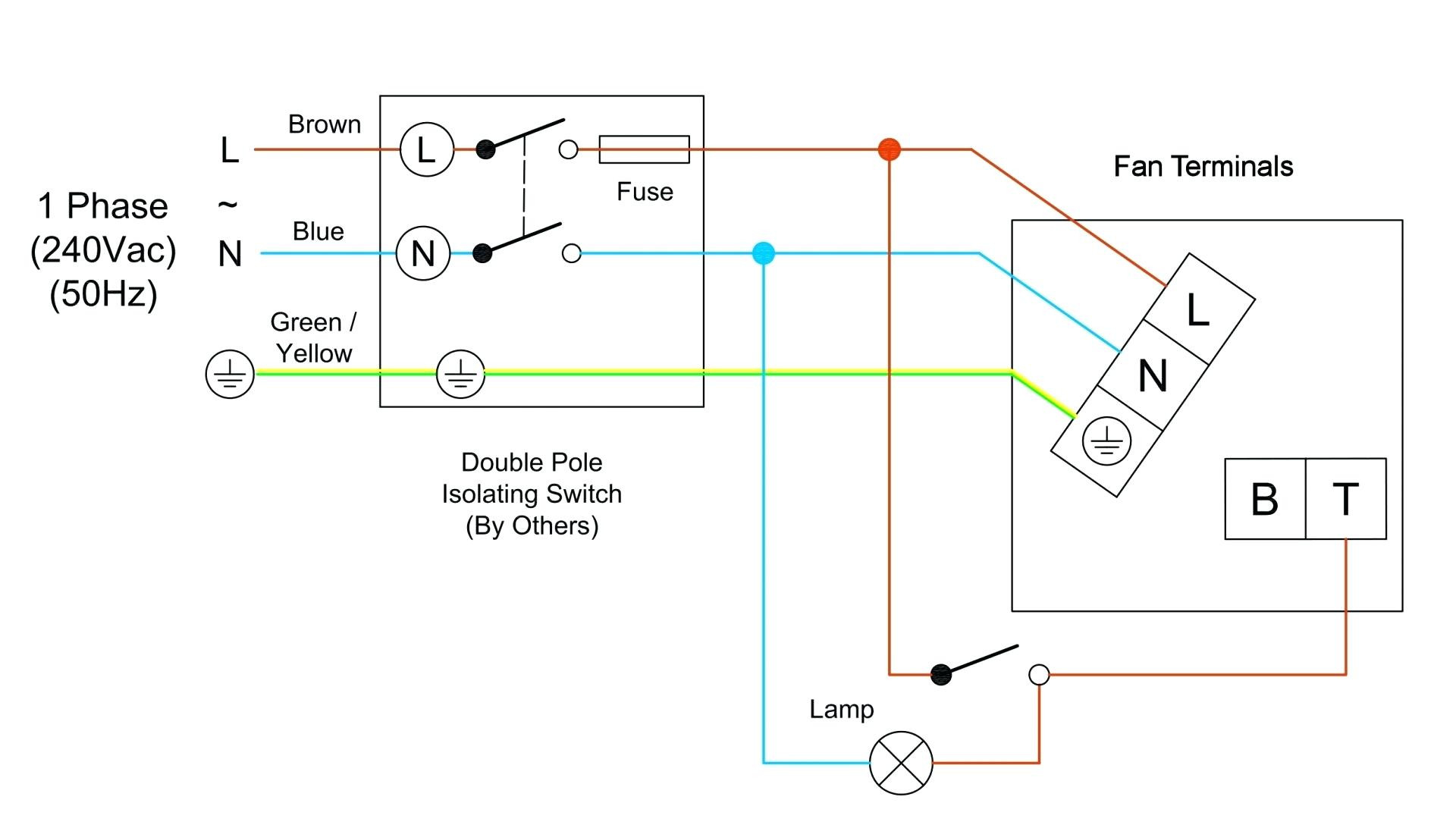
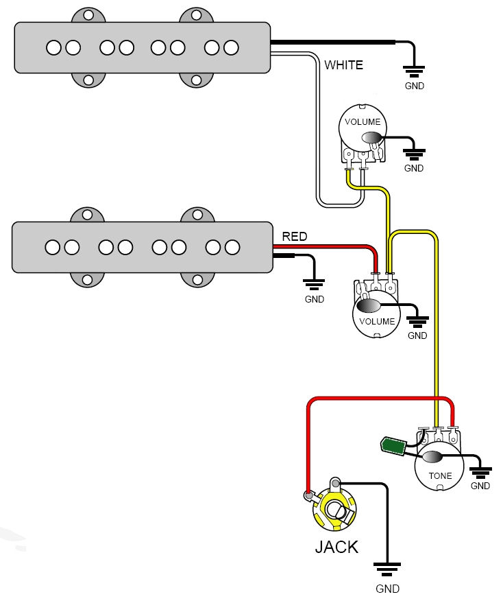
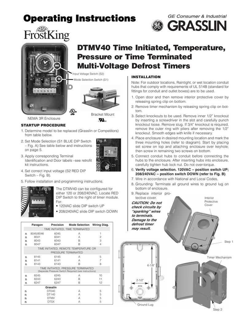
Paragon defrost timer 8141 00 wiring. Collection of paragon defrost timer 8145 20 wiring diagram.
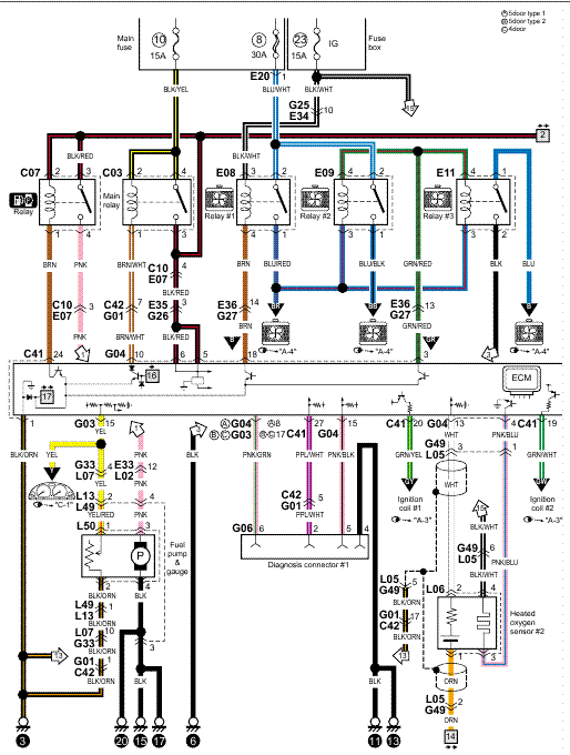
Paragon 8145 20 Wiring Diagram
Hot gas or compressor shutdown.

Paragon 8145 00 wiring diagram. Awesome 20 defrost timer wiring diagram ideas electrical img source: They accommodate various types of defrost systems including electric defrost heaters, hot gas and compressor off cycle. Schematron.org paragon 00 wiring diagram keeprite service parts all categories printout 05da cylinder head gasket use 05ga 06cyj pressor p cool 3 60 oil less 06da solenoid coil v 06da o pump&bearing pkg.
Wiring diagrams electric heat defrosting s & s series. 4 to minutes in s and paragon wiring diagrams electric heat defrosting s & s series. (on most models it is riveted to the side of the switch box.) enter the data plate p/n number in the search box above the table.
Electric heat, hot gas or compressor shutdown. At four defrosts per day, the paragon universal defrost timer switches last 16 years longer than competitive offerings. 8145 20 timer wiring diagram.
S s s wiring diagrams electric heat defrosting s & s series. Applications and wiring diagrams mechanical defrost timer 8000 series. The paragon® 8000 series commercial defrost controls are designed for commercial freezers and refrigerators to provide automatic defrost capability.
Wiring using 120v or 240v single phase fine compressor voltage common to timer. Tors, paragon® commercial defrost controls choice tm in defrost timers. If your data plate does not have a p/n number, then enter the kiln model number shown on the data plate.
They accommodate various types of defrost systems including electric defrost heaters, hot gas, and compressor off cycle. It reveals the elements of the circuit as simplified forms and also the power and also signal connections between the tools. All documents are in pdf format.
40 amps, 2 hp positive slider bar switch design assures positive electrical contact and wipes the contact surface of contaminates temperature or pressure terminated models are designed for defrost termination using an. The paragon® defrost and the tork® electric timers offer versatility and unbeatable electric heat,. Intermatic 22tgr, surface mount bracket for intermatic timers 22tgr bracket paragon v wiring manual.
Paragon 8145 20 defrost timer wiring diagram. Applications and wiring diagrams mechanical defrost timer 8000 series customer service telephone 1.800.304.6563 customer service facsimile 1.800.426.0804 hvaccustomerservice@robertshaw.com 8047 20 208 240 for electric heat defrosting auxiliary contact models 50 hz available open open closed 4 110 min.
To search for a wiring diagram, refer to the data plate on your kiln. On paragon 8145 20 defrost timer wiring diagram. One to six times per day.
It shows the components of the circuit as simplified shapes, and the gift and signal connections with the devices. Tors, paragon ® commercial defrost.

Paragon 8145 00 Wiring Diagram Sample

Paragon 8145 00 Wiring Diagram easywiring

Paragon Defrost Timer 814500 Wiring Diagram

Paragon 8145 00 Wiring Diagram Sample

30 Paragon Defrost Timer Wiring Diagram Wiring Diagram List
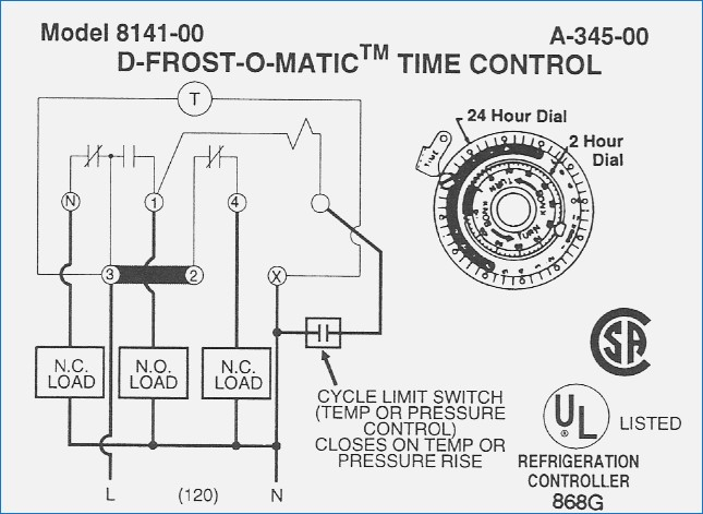
[DIAGRAM] Refrigerator Defrost Timer Wiring Diagram FULL Version HD Quality Wiring Diagram

Paragon 8145 00 Wiring Diagram easywiring

Paragon 8145 00 Wiring Diagram Sample
Paragon Defrost Timer Wiring Diagram SAMIHAH88

Paragon 8145 00 Wiring Diagram Sample
Paragon 8141 00 Wiring Diagram Atkinsjewelry

Paragon 8145 00 Wiring Diagram Sample

Paragon Defrost Timer 8145 20 Wiring Diagram

Paragon Defrost Timer 8141 00 Wiring Speed Tutor
Paragon 8141 00 Wiring Diagram Free Wiring Diagram
